Sunday, April 23, 2017

PH Module Hiatus

Hello all,

I have said I would release another ph module in the past. The initial designs are made and all of the files are sitting on a backed up disk, but years later my engineering bench is still collecting dust right where I left off.

Everything is well, its just that life has been pulling me in a different direction for quite a while now and I've made the decision to just let that happen for the foreseeable future.

            Reza

Saturday, July 12, 2014

Measuring PH with Dormant Labs PH Module V2 Using 10 & 7 calibration solutions

Here is another setup guide that shows how to measure PH using the Dormant Labs PH Module V2, except this time we will calibrate using 10 & 7 ph calibration solutions.

You will need

  • 10 ph calibration solution
  • 7 ph calibration solution
  • Dormant Labs PH Module V2
  • A PH probe
  • 4 dupont female to male cables
  • An Arduino
  • Containers to hold the PH calibration solutions, and a container to rinse the ph probe with water.

Fill one cup with 10 PH calibration solution, one cup with 7 ph calibration solution, and one cup with water.


Connect the ph probe to the module.


Connect the module SDA,SCL pins to the Arduino SCL and SDA pins, here because we are using a mega, the SCL is pin 21, and SDA is pin 20. Then connect VCC to 5v on the arduino mega, and then connect GND to the GND pin on the arduino mega.

Then connect the arduino mega to your computer.

Now we will upload the source code. Get the source code from here:

and upload it using the Arduino IDE, if you do not have the arduino IDE then get it from the arduino site.


After uploading the code, open the serial monitor and you should see something like this:


It will output the wrong reading until we calibrate it, so lets do that.

First rinse off the ph probe in the tap water.


Now dip it in the PH 7 calibration solution, and write down the value for avgPhVolts that comes up in the serial monitor.


Now rinse it again.


Now dip it in the PH 10 calibration solution and write down the value for avgPhVolts in the serial monitor.


Also write down the avgRoomTempC value that appears in the serial monitor.

Here are the values that I got:


Now enter them for the values of volt7, volt10, and calibrationTempC and upload.


You now have calibrated your ph sensor! Edit the program to do whatever you want now.

Sunday, April 20, 2014

LCD Display with Dormant Labs PH Module V2

This is a stepping stone tutorial, and comes after first learning to measure PH, you should review this tutorial first.

For my own purposes I do want the arduino to show ph on a screen, without it being connected to a computer. This is the way I went about it.

The LCD I got is a "I2C 0.96" OLED display (for Arduino /PIC /AVR ) Blue/Yellow color" from the ebay seller "wide.hk."


So I soldered some 2.54mm pitch pin headers to the lcd, then super glued it to the back of the ph module.


I then connected and soldered the SDA, SCL, VCC, GND pins of the lcd to the SDA, SCL, VCC, and GND pads on the ph module. 


I should note that I only used dupont cables because I had already soldered headers. If I was going to do it again I would just solder wires to both ends. Also, the area I applied the superglue to was the inductor.

So connect the SDA,SCL,VCC,GND pins of the ph module to your Arduino. After that, load up this code through the arduino IDE:

https://gist.github.com/rezahussain/11128896

Follow the same calibration instructions as in the previous tutorial and now your arduino will display the ph on a screen.


Thursday, April 3, 2014

Measuring pH using Dormant Labs PH Module V2 and Arduino

Here is a quick setup guide to start measuring ph using the Dormant Labs PH Module V2.

You will need:
  • PH 4 and 7 Calibration Solution
  • A Arduino
  • Dormant Labs PH Module V2 (available here)
  • A PH Probe
  • Three small cups, two to hold the two calibration solutions, and one to hold water for rinsing the ph probe 
  • 4 dupont male to female cables

First connect the ph probe to the ph module


Then
  • Connect V+ to Arduino 5v or 3v pin
  • Connect GND to Arduino GND pin
  • Connect SDA to Arduino SDA pin(For UNO it is A4)
  • Connect SCL to Arduino SCL pin (For UNO it is A5)
  • Attach USB to Arduino


Get the source code from here:
https://gist.github.com/rezahussain/bb7715534688d8dc0520

and upload it using the Arduino IDE. If you do not have the arduino IDE get it from the arduino site.

After uploading the code, open the serial monitor and you should see output like this:


You are now ready to calibrate your ph probe.

Fill one cup with PH 4.0 calibration solution, one with 7.0 calibration solution, and a third with water.
Remove the cover from the ph probe and rinse it with water.


Then dip the probe in the 4.0 solution, swirl it around for a little bit, and write down the value you see for the avgPhVolts. For me, I saw 0.95v.


Rinse the ph probe in the water, then dip in the 7.0 calibration solution and write down what you see for avgPhVolts.


Here are the values I got:


Now I replace the volt4, volt7, and calibrationTempC, then re-upload to the Arduino.


After re-uploading your probe is now calibrated! The serial monitor of the arduino IDE will show the correct information. Edit the code as you like now.

Sunday, March 16, 2014

PCDuino Primer

I have considered and evaluated several mcu functionality+wifi boards, and 'pcduino lite wifi' is the board I chose to proceed forward with.

It is an ARM cpu running Linaro 12.07. What you need to get started is an hdmi cable for video, a usb hub, mouse and keyboard, and then a 'USB Cable A-micro' usb cable.


The default username for the pcduino is 'ubuntu'. On startup press F8, and then set the password.


The next step is to get the pcduino to connect to your home wireless network, this is the easiest way:


But you should assign it a static ip. These are the settings I used.


I set the pcduino to have an ip of 192.168.1.216 on my local wifi network.


And my wifi network is using WPA2 security, so there are these settings:


Now with those steps done, I can remotely ssh into the pcduino to do any administration/coding that I need to do. On my mac I opened up the terminal app:

Then enter in the password that you specified for the ubuntu user, and you are in. Now you only have to have power connected to the pcduino to put and run code on it.

Once you ssh in, install nano by typing

sudo apt-get install nano

Now lets setup arduino style programming:

cd ~
mkdir rezaWork
cd rezaWork
git clone http://github.com/pcduino/c_environment
cd c_environment
make

This compiles all of the sample arduino programs.
Lets run the blink example:

cd output
cd test
./linker_led_test 13


The LED on the board blinks.


If you wanna change the blink time:

cd ~
cd rezaWork
cd c_environment
cd sample
nano linker_led_test.c

Now change the blink delay, then save and exit out of nano.
Now you have to recompile and run:

cd ~
cd rezaWork
cd c_environment
make
cd output
cd test
./linker_led_test 13


The LED now blinks at whatever interval you set it to.

Monday, January 20, 2014

Compiling objective-c 2.0 with Foundation on Freebsd 9.1

This was harder than xubuntu, so here is the corresponding how to.

1. Install necessary packages
pkg_add -r subversion
pkg_add -r libffi
pkg_add -r libicu
pkg_add -r nano

2. Install libobjc2
cd ~
mkdir tempSetup
svn co svn://svn.gna.org/svn/gnustep/libs/libobjc2/trunk libobjc2
cd libobjc2
setenv CC /usr/bin/clang
setenv CXX /usr/bin/clang++
make

3. Install gnustep tools
cd ..
svn co svn://theraven@svn.gna.org/svn/gnustep/tools/make/trunk make
cd make
./configure -enable-debug-by-default
gmake install

Note the output for the next step:

Creating system tools directory: /usr/local/bin
Creating makefile directories in: /usr/local/share/GNUstep/Makefiles
Installing GNUstep configuration file in /usr/local/etc/GNUstep/GNUstep.conf
Installing gnustep-make support software
Installing makefiles
Installing Test Framework scripts
Installing Test Framework support files

Installing (and compressing) manpages


chmod 755 ./usr/local/share/GNUstep/Makefiles/GNUstep.csh
./usr/local/share/GNUstep/makefiles/GNUstep.csh
echo ./usr/local/share/GNUstep/Makefiles/GNUstep.csh >> ~/.profile

4. Install gnustep base
cd ..
svn co svn://svn.gna.org/svn/gnustep/libs/base/trunk base
cd base
./configure --disable-mixedabi CC=/usr/bin/clang CXX=/usr/bin/clang++
gmake install

5. Make a test program
cd ~
mkdir testapp
cd testapp
nano test.m
#import <Foundation/Foundation.h>
int main(int argc, const char *argv[])
{
   @autoreleasepool
   {
      NSLog(@"Helloworld");
   }
   return 0;
}
exit nano and save

6. Create the makefile

nano GNUmakefile

GNUSTEP_MAKEFILES=/usr/local/share/GNUstep/Makefiles

include $(GNUSTEP_MAKEFILES)/common.make

TOOL_NAME = test
test_OBJC_FILES = test.m

include $(GNUSTEP_MAKEFILES)/tool.make


exit nano and save


11. Make and run the test
gmake
cd obj
./test

References:
https://forums.freebsd.org/viewtopic.php?&t=39466
http://etoileos.com/downloads/installtrunk/freebsd/


Saturday, December 28, 2013

Compiling obj-c 2.0 with Foundation Kit on xubuntu 12.04 LTS with clang & llvm

This was tricky for me, so I am posting a guide as usual.

1. sudo apt-get install subversion
2. sudo apt-get install build-essential
3. sudo apt-get install pacman
4. sudo apt-get install libobjc2
5. sudo apt-get install clang

6. Then follow the instructions here:
        http://clang.llvm.org/get_started.html


Here is a sample program:

#import <Foundation/Foundation.h>

int main(int argc, const char * argv[])
{

    @autoreleasepool {
        
        // insert code here...
        NSLog(@"Hello, World!");
        
    }
    return 0;

}

Save it as main.m and to compile it do:

sudo clang main.m `gnustep-config --objc-flags` `gnustep-config --objc-libs` -x objective-c -fconstant-string-class=NSConstantString -fobjc-nonfragile-abi -fblocks -lgnustep-base -lgnustep-gui -ldispatch -I /usr/include/GNUstep -L /usr/lib/GNUstep

it will create a file called a.out, to run it do:

sudo ./a.out

References:
http://sohanikh.blogspot.com/2013/02/how-to-build-llvm-from-source-on-ubuntu.html
http://clang.llvm.org/get_started.html
http://stackoverflow.com/questions/14921482/clang-compiling-error-undefined-reference-to-objc-autoreleasepoolpush

Saturday, December 14, 2013

3930k GA-x79-UP5 Hackintosh 10.9 Mavericks

There was some trouble for me to get this up and running, so I am posting some clarifications on how to do it.

1. The ram that you choose doesn't matter, at least in my experience, I tried 4 different brands at different speeds and they all worked.
The motherboard does matter, I tried with an ASRock x79 Extreme4 and couldn't enter the installer.

2. I used 
tonymacx86's guide:
http://www.tonymacx86.com/374-unibeast-install-os-x-mavericks-any-supported-intel-based-pc.html

And Dingleberry's guide:
http://www.tonymacx86.com/user-builds/93089-new-success-dingleberrys-content-creator-build-ga-x79s-up5-x79-c606-i7-3930k-32gb-gtx670.html

4. For GPU I got a ASUS nvidia 240 gt off of ebay for 60$.
    For mobo I used GA-x79-UP5 off of ebay for 220$.
    For CPU 3930k
    Everything else choice doesn't matter(case,psu,hd etc)

5. When starting up, and you get to the screen where you can choose to boot from your usb stick, you need to type in 

-v GraphicsEnabler=No npci=0x3000 cpus=1

Then hit enter.
This isn't listed in the guide and is necessary to progress.

6. In verbose mode when you get to the part where it says cannot load bootcache just wait, it takes a little bit to progress to the next part.


7. After you go through the general guide you need to disable EIST in the bios, and then apply the VoodooTSCSync.kext using KextBeast, both are in Dingleberry's post. Disabling EIST will run your cpu at what you set it in the bios instead of 1.3Ghz, and VoodooTSCSync.kext is supposed to enable all six cores on the 3930k so you do not have to boot with cpus=1.

8. Setup I used:


9. Right now I am still booting with -v GraphicsEnabler=No npci=0x3000,
but you can edit the org.chameleon.Boot.plist, and put '-v GraphicsEnabler=No npci=0x3000' for the string under the 'Kernel Flags' key. Then you don't need to type anything when the comp boots up.


10. To get sound working use this link
http://www.tonymacx86.com/audio/99315-ga-x79s-up5-ml-10-8-3-3970x-no-sound.html


Good luck!


Saturday, December 7, 2013

BFL Jalapeno Xubuntu Mining

In April 2013, I saw that asics were shipping for mining bitcoin. I ordered a Jalapeno, which came in Sept 2013. After mining with it for about two weeks using cgminer for OSX I tried to sell it on ebay, but people would just keep bidding and not paying after the auction ended.

So I set it up on my linux server to mine and here are the steps to do it.

I had help from reading this guide, I am going to copy and paste some of the steps incase that page disappears so this guide doesn't become fragmented.

https://coinaxis.com/index.php/tutorials/entry/how-to-configure-linux-and-build-cgminer-for-bitcoin-and-litecoin

1. Create a usb install key for Xubuntu 12.04 using 'linux live usb creator' on Windows.
2. Install it on a pc and boot to it.
3. Open a Terminal window and type these commands

sudo apt-get install libcurl4-openssl-dev pkg-config libtool libncurses5-dev libudev-dev screen xterm
sudo apt-get install git-core
sudo apt-get install openssh-server byobu
sudo apt-get install autoconf
sudo apt-get install automake

git clone https://github.com/ckolivas/cgminer
cd cgminer
./autogen.sh

CFLAGS="-O2 -Wall -march=native" ./configure --enable-scrypt --enable-bflsc --enable-bitforce
sudo make
sudo make install

sudo usermod -G plugdev -a yourusernamehere

sudo cp 01-cgminer.rules /etc/udev/rules.d/

sudo reboot


4. After reboot open another terminal window and type


cd cgminer
./cgminer


5. Then enter in your pool information. If you want to mine bitcoin make an account at btcguild.com. I am going to use the asic to mine Peercoin and will evaluate some pools before I post one here.


Wednesday, June 26, 2013

Dormant Labs AC Wifi Outlet Setup


This guide will show how to setup the Dormant Labs AC Wifi Outlet. This outlet is an ac outlet that can be turned on and off from your wifi network.


1. The first step is to configure the outlet so it can connect to your wifi network. There is a switch on the side of the outlet, make sure it is in the left position. This sets the outlet to configuration mode.


2. Plug the outlet into power.


3. The outlet will blink the blue and amber lights up to 7 times as it runs it's boot sequence. Wait until this is done.


4. When in configuration mode, the outlet creates it's own wifi network. You need to have your computer connect to the outlet's wifi network to access the configuration page. Join the outlet's wifi network.


5. The outlet is configured through a URL. The format goes like this:


http://169.254.1.1/configure/yourSSIDName/wifipassword/last3digitsIPaddress


So if I wanted to setup the outlet to connect to my home wifi network I would gather my settings:

WifiNetwork = ASUS
WifiPassword = ASUS123
MyDesiredIP = 111 (so the final ip would be 192.168.1.111, it has to be 3 digits, starting from 101)

I could pick 168, 333, 222, etc if I wanted to.

Then I would go into a browser and enter in the url. This is the result page that I get. The outlet is configured.


6. Unplug the outlet


7. Now put the switch into the right position. This puts it in operational mode.


8. Re plug in the outlet


9. The outlet will blink the blue and amber lights up to 7 times as it connects to your wifi network.


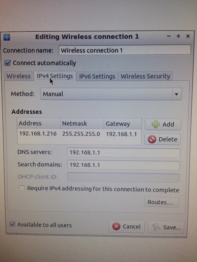
10. You should now connect your computer to the same wifi network if you haven't yet.


11. Connect the output cable to the outlet.


12. For testing purposes I connect the outlet cord to a lamp.

13. Now to turn the outlet on and off, you open a browser and type in the following:

http://192.168.1.111/TurnOn
http://192.168.1.111/TurnOff

When the outlet is activated it has a green light that turns on.(It also turns on the connected lamp)


Remember, the address is 192.168.1.XXX , where XXX is the last three digits that you chose in the configuration step.

This outlet was designed to be easily configurable, and to be easily scriptable. Scripts on your computer can call the turnOn/turnOff URLs to activate and deactivate this ac wifi outlet.

Enjoy!